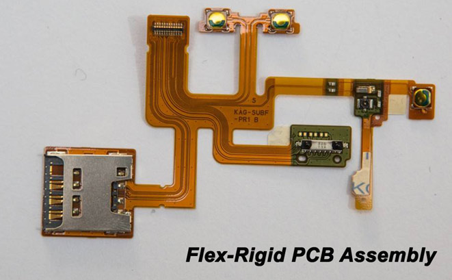
Rigid-Flex printed circuit boards are designed to provide solutions, and act as replacements for rigid PCBs. As the
name suggests, these circuit boards are a hybrid of flex and rigid circuits. The advantage of this type is that they
exhibit the benefits of both rigid as well as flexible circuit boards.Most rigid-flex circuit boards consist of multiple
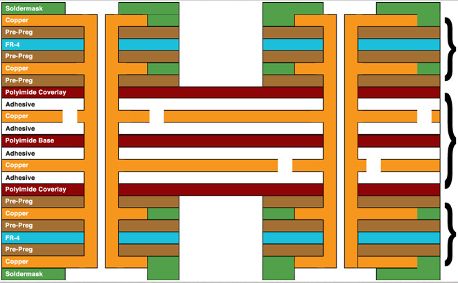
layers of flexible circuit substrates attached to rigid boards externally and/or internally. The flexible substrates
are designed to be in a constant state of flex, and are usually formed in a flexed curve during manufacturing or
installation. This is dependent upon the design of the application

according to a three-dimensional environment that also provides high spatial efficiency.
board.
board.
among the units. In its place, the flex circuitry electrically joins the scheme together.
FR4 (Flame Retardant) or polyimide.

| No. | Item | Description | Data and Model | ||||||
| 1 | FPC Main material | Brand | taiflex、graceth)、SY | ||||||
| 2 | PCB Material | Brand | SY、ITEQ、KB | ||||||
| 3 | Texture | Texture Brand | PI、 PET | ||||||
| 4 | Cover Film | Brand | taiflex、graceth、SY | ||||||
| 5 | Max Layers | LAYER | 1-56layers(sample)、1-48layers(manufacture) | ||||||
| 6 | Finish Board thickness | mm | 0.25-6.0mm(samplel) Rigid – Flex PCB 0.25-6.0mm | ||||||
| 7 | Min Pattern Width / Spacing | mm | 0.05mm/0.05mm | ||||||
| 8 | Max finish board size | mm | 230*450mm | ||||||
| 9 | Finish Board thickness tolerance | mm | ±50.05mm | ||||||
| 10 | PP Thickness | um | 12.5um 、 25um 、 50um | ||||||
| 11 | Copper thickness | um | 12um 、 18um 、 36um 、 70um | ||||||
| 12 | Stiffener materail | Variety | FR4/PI/PET/SUS/PSA | ||||||
| 13 | Surface treatment | Variety | ENIG、Immersion tin、OSP、immersion silver、plating gold | ||||||
| 14 | Min hole size | mm | Mechanical Hole :0.15mm 、Laser Hole0.1mm | ||||||
| 15 | Hole tolerance | mm | NPTH:±0.05mm 、PTH:±0.075mm | ||||||
| 16 | Cover film color | Variety | Yellow 、 Black | ||||||
| 17 | PI thickness | mil | 0.5mil、0.7mil、0.8mil、1mil、2mil | ||||||
| 18 | Max number of layers of FPCB | 1-8layers | |||||||
| 19 | Min finished size | mm | 5mm*8mm | ||||||
| 1/2 | |||||||||
| 20 | Min pad | mm | inner layer(5mil)、outer layer(4mil) | |
| 21 | Stiffener min size | mm | 4mm×5mm | |
| 22 | Stiffener max size | mm | 32mm×32mm | |
| 23 | Stifferner alignment accuracy | mm | ±0.075mm | |
| 24 | Cover minimum openning size | mm | 0.6×0.6mm(steeling tooling)、0.5×0.5mm(Precision tooling) | |
| 25 | Minimum openning spacing for covering film | mm | 0.5mm(Precision tooling)、0.2mm(Laser Routing)、 | |
| 0.15mm(Normal drilling) | ||||
| 26 | Coating film overflow amount(unilateral) | mm | Normal0.08-0.12mm 、 Limitation0.03mm | |
| 27 | Min diameter of gold finger semicircle hole | mm | 0.25mm,Normal value0.3mm | |
| 28 | Rigid-Flex PCB:Peel-off strength | N | 1.4N | |
| 29 | Rigid-Flex PCB:Planeness | um | Less than 15um before baking; less than 30um after baking | |
| 30 | Rigid-Flex PCB:thermal shock | ℃ | 288℃(3 times within 10 seconds) | |
| 31 | Rigid-Flex PCB:W/B gold wire pull | g | > 6g | |
| strength | ||||
| 32 | Rigid-Flex PCB:min.board thickness | mm | FPCB 0.1mm、4Layers 0.3mm、6Layers 0.5mm、8Layers 0.6mm、 | |
| 10Layers0.8mm | ||||